Point of Selection
Table 6 to Tablel 10 show accuracy standards for the mounting surfaces of the precision Ball Screw.
Table 6 Radial Runout of the Circumference of the Thread Root In Relation to the Supporting Portion Axis of the Screw Shaft.
| Screw shaft outer diameter (mm) | Runout (maximum) | ||||||
|---|---|---|---|---|---|---|---|
| Above | Or less | C0 | C1 | C2 | C3 | C5 | C7 |
| - | 8 | 3 | 5 | 7 | 8 | 10 | 14 |
| 8 | 12 | 4 | 5 | 7 | 8 | 11 | 14 |
| 12 | 20 | 4 | 6 | 8 | 9 | 12 | 14 |
| 20 | 32 | 5 | 7 | 9 | 10 | 13 | 20 |
| 32 | 50 | 6 | 8 | 10 | 12 | 15 | 20 |
| 50 | 80 | 7 | 9 | 11 | 13 | 17 | 20 |
| 80 | 100 | - | 10 | 12 | 15 | 20 | 30 |
Unit : µm
Note : The measurements on these items include the effect of the runout of the screw shaft diameter. Therefore, it is necessary to obtain the correction value from the overall runout of the screw shaft axis, using the ratio of the distance between the fulcrum and measurement point to the overall screw shaft length, and add the obtained value to the table above.
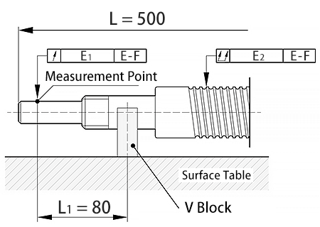
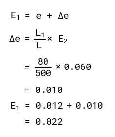
e : Standard value in Table 6 (0.012)
Δe : Correction value
E2 : Overall radial runout of the screw shaft axis (0.060)
L L1 80 500 0.060 0.010
Δe = × E2 = e + Δe
E1 = 0.012 + 0.010 = 0.022
Table 7 Perpendicularity of the Supporting Portion End of the Screw Shaft to the Supporting Portion Axis
| Screw Shaft outer diameter (mm) | Perpendicularity (maximum) | ||||||
|---|---|---|---|---|---|---|---|
| Above | Or less | C0 | C1 | C2 | C3 | C5 | C7 |
| - | 8 | 2 | 3 | 3 | 4 | 5 | 7 |
| 8 | 12 | 2 | 3 | 3 | 4 | 5 | 7 |
| 12 | 20 | 2 | 3 | 3 | 4 | 5 | 7 |
| 20 | 32 | 2 | 3 | 3 | 4 | 5 | 7 |
| 32 | 50 | 2 | 3 | 3 | 4 | 5 | 8 |
| 50 | 80 | 3 | 4 | 4 | 5 | 7 | 10 |
| 80 | 100 | - | 4 | 5 | 6 | 8 | 11 |
Unit : µm
Table 8 Perpendicularity of the Flange Mounting Surface of the Screw Shaft to the Screw Shaft Axis
| Nut diameter (mm) | Perpendicularity (maximum) | ||||||
|---|---|---|---|---|---|---|---|
| Above | Or less | C0 | C1 | C2 | C3 | C5 | C7 |
| - | 20 | 5 | 6 | 7 | 8 | 10 | 14 |
| 20 | 32 | 5 | 6 | 7 | 8 | 10 | 14 |
| 32 | 50 | 6 | 7 | 8 | 8 | 11 | 18 |
| 50 | 80 | 7 | 8 | 9 | 10 | 13 | 18 |
| 80 | 125 | 7 | 9 | 10 | 12 | 15 | 20 |
| 125 | 160 | 8 | 10 | 11 | 13 | 17 | 20 |
| 160 | 200 | - | 11 | 12 | 14 | 18 | 25 |
Unit : µm
Table 9 Radial Runout of the Nut Circumference in Relation to the Screw Shaft Axis
| Nut diameter (mm) | Runout (maximum) | ||||||
|---|---|---|---|---|---|---|---|
| Above | Or less | C0 | C1 | C2 | C3 | C5 | C7 |
| - | 20 | 5 | 6 | 7 | 9 | 12 | 20 |
| 20 | 32 | 6 | 7 | 8 | 10 | 12 | 20 |
| 32 | 50 | 7 | 8 | 10 | 12 | 15 | 30 |
| 50 | 80 | 8 | 10 | 12 | 15 | 19 | 30 |
| 80 | 125 | 9 | 12 | 16 | 20 | 27 | 40 |
| 125 | 160 | 10 | 13 | 17 | 22 | 30 | 40 |
| 160 | 200 | - | 16 | 20 | 25 | 34 | 50 |
Unit : µm
Table 10 Parallelism of the Nut Circumference (Flat Mounting Surface) to the Screw Shaft Axis
| Mounting reference length (mm) | Parallelism (maximum) | ||||||
|---|---|---|---|---|---|---|---|
| Above | Or less | C0 | C1 | C2 | C3 | C5 | C7 |
| - | 50 | 5 | 6 | 7 | 8 | 10 | 17 |
| 50 | 100 | 7 | 8 | 9 | 10 | 13 | 17 |
| 100 | 200 | - | 10 | 11 | 13 | 17 | 30 |
Unit : µm
Method for Measuring Accuracy of the Mounting Surface
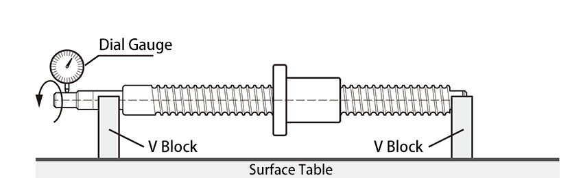
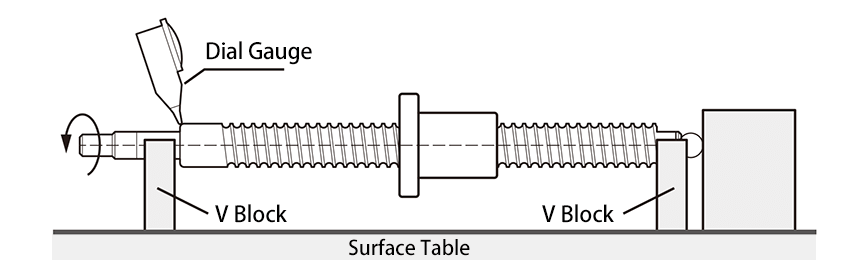
1 Radial Runout of the Circumference of the Motor-mounting Shaft-end in Relation to the Bearing Journals of the Screw Shaft.
Table 6 Support the end journal of the screw shaft on V blocks. Place a probe on the circumference of the motor-mounting shaft-end, and record the largest difference on the dial gauge as a measurement while rotating the screw shaft through one revolution.
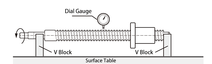
2 Radial Runout of the Circumference of the Raceway Threads in Relation to the Bearing Journals of the Screw Shaft
Table 6 Support the end journal of the screw shaft on V blocks. Place a probe on the circumference of the nut, and record the largest difference on the dial gauge as a measurement while rotating the screw shaft by one revolution without rotating the nut.
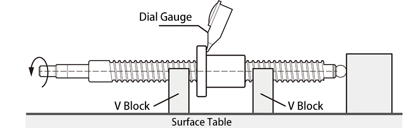
3 Perpendicularity of the End Journal of the Screw Shaft to the Bearing Journals
Table 7 Support the bearing journal portions of the screw shaft on V blocks. Place a probe on the screw shaft's supporting portion end, and record the largest difference on the dial gauge as a measurement while rotating the screw shaft through one revolution.
4 Perpendicularity of the Flange Mounting Surface of the Screw Shaft to the Bearing Journals
Table 8 Support the thread of the screw shaft on V blocks near the nut. Place a probe on the flange end, the screw shaft and the nut through one revolution.
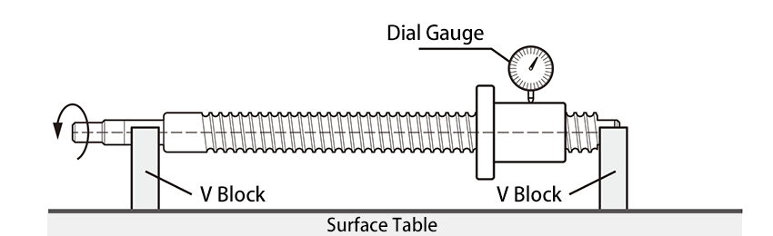
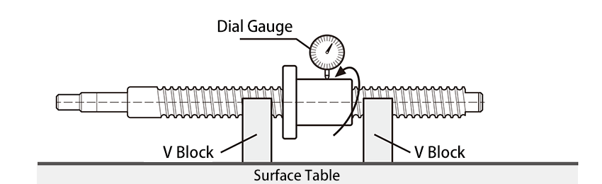
5 Radial Runout of the Nut Circumference in Relation to the Screw Shaft Axis
Table 9 Support the thread of the screw shaft on V blocks near the nut. Place a probe on the circumference of the nut, and record the largest difference on the dial gauge as a measurement while rotating the nut through one revolution without rotating the screw shaft.
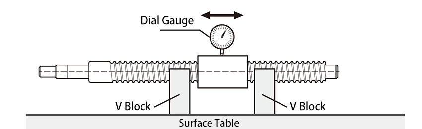
6 Parallelism of the Nut Circumference (Flat Mounting Surface) to the Screw Shaft Axis
Table 10 Support the thread of the screw shaft on V blocks near the nut. Place a probe on the circumference of the nut (flat mounting surface), and record the largest difference on the dial gauge as a measurement while moving the dial gauge in parallel with the screw shaft.
7 Overall Radial Runout of the Screw Shaft Axis
Support the supporting portion of the screw shaft on V blocks. Place a probe on the circumference of the screw shaft, and record the largest difference on the dial gauge at several points in the axial directions as a measurement while rotating the screw shaft through one revolution.
Note : For the overall radial runout of the screw shaft axis, refer to JIS B 1192-1997.